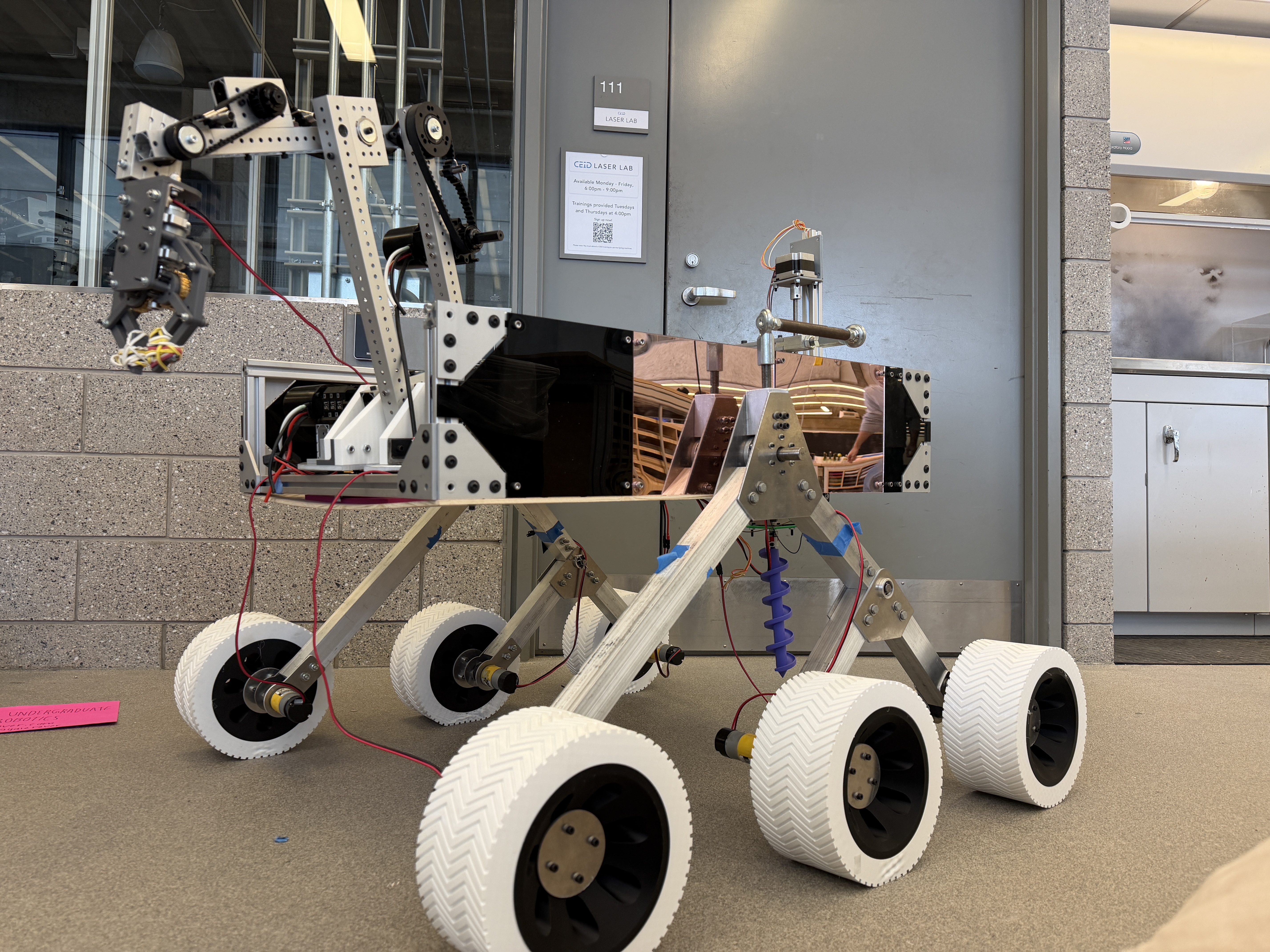
Linear Actuators for Instrument Deployment
I designed a set of custom ball-screw linear actuators to position scientific instruments for the rover's autonomous life-detection system. These actuators needed to be lightweight, modular, and provide enough torque for controlled deployment of augers, scoops, and sensors across varied terrain.
The system includes two vertical lift units and a sliding linear stage, all built from aluminum components, custom brackets, and standard NEMA stepper motors. Together they give the rover the ability to raise, lower, and position its detection instruments during soil sampling and analysis tasks.
Because the project operated under a strict budget, I designed around reusing T-slot extrusions from the rover chassis and lead screws salvaged from old 3D printers — significantly reducing materials cost. The modular layout also makes it fast to swap hardware between testing iterations and competition runs.
// what I did
- Designed the full actuator geometry for two vertical lift units and one horizontal linear stage
- Reused T-slot extrusions and 3D-printer lead screws to keep costs within team budget
- Created all CAD models for actuator assemblies, brackets, and mounting plates in SolidWorks
- Performed preliminary FEA to assess column stiffness and minimize deformation under load
- Selected motors based on force, speed, torque, and duty cycle requirements
- Optimized structural layout for rigidity, low weight, and ease of manufacturing
- Validated clearance, stroke length, and full motion range for each detection instrument
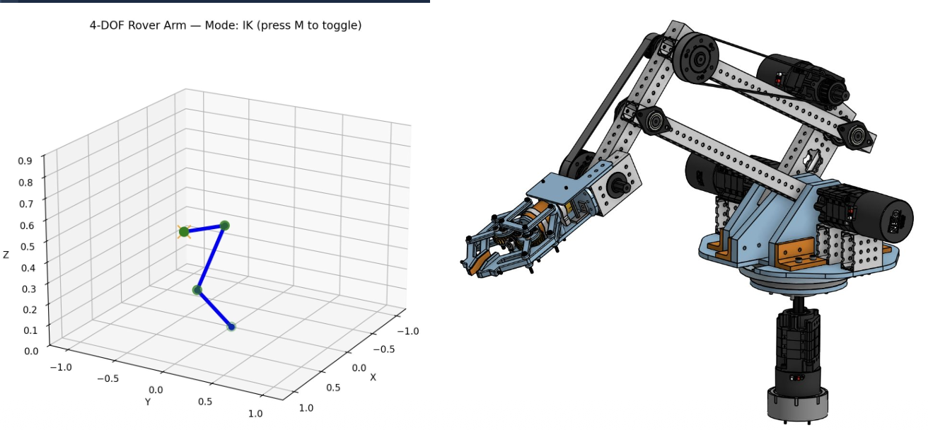
4-DoF Kinematic Simulator
To validate the rover arm's mechanical design before committing to fabrication, I developed a full forward and inverse kinematics simulator in Python. The simulator models joint angles, link lengths, and end-effector pose, and computes the reachable workspace in real time for the arm's intended sampling tasks.
This tool let the team verify that the manipulator could reach ground targets, avoid self-collision, and maintain proper tool orientation — all without building expensive physical prototypes. It also supported trajectory planning for autonomous operation and a manual control mode for practicing real-life arm operation before competition.
// what I did
- Built the full forward kinematics chain using Denavit–Hartenberg transformation matrices
- Implemented an inverse kinematics solver to compute joint angles from arbitrary target poses
- Simulated the arm's workspace and validated reachability for soil-sampling tasks
- Added real-time collision avoidance checks and joint-limit enforcement
- Created 3D visualizations to evaluate end-effector motion and tool alignment
- Used simulation results to finalize hardware component selection for the physical arm